Easy Rotator Control ERC Version 4 USB with Yaesu G-450ADC
I completed the ERC Version 4 USB kit from Vibroplex this week. The kit comes with a CD for the calibration and test software, plus a PDF folder that has the kit assembly instructions and installation guidelines to mount the board inside the control box for specific rotators.
The kit was easy to build, but getting it working with my rotator took a bit more work. Specific pin outs and solder points are not documented - you have to determine that on your own. The theory of operations is discussed, and schematics for many rotators are provided, but I needed to use a voltmeter and a little of of trial and error to correctly wire the ERC board to the Yaesu G-450ADC rotator controller.
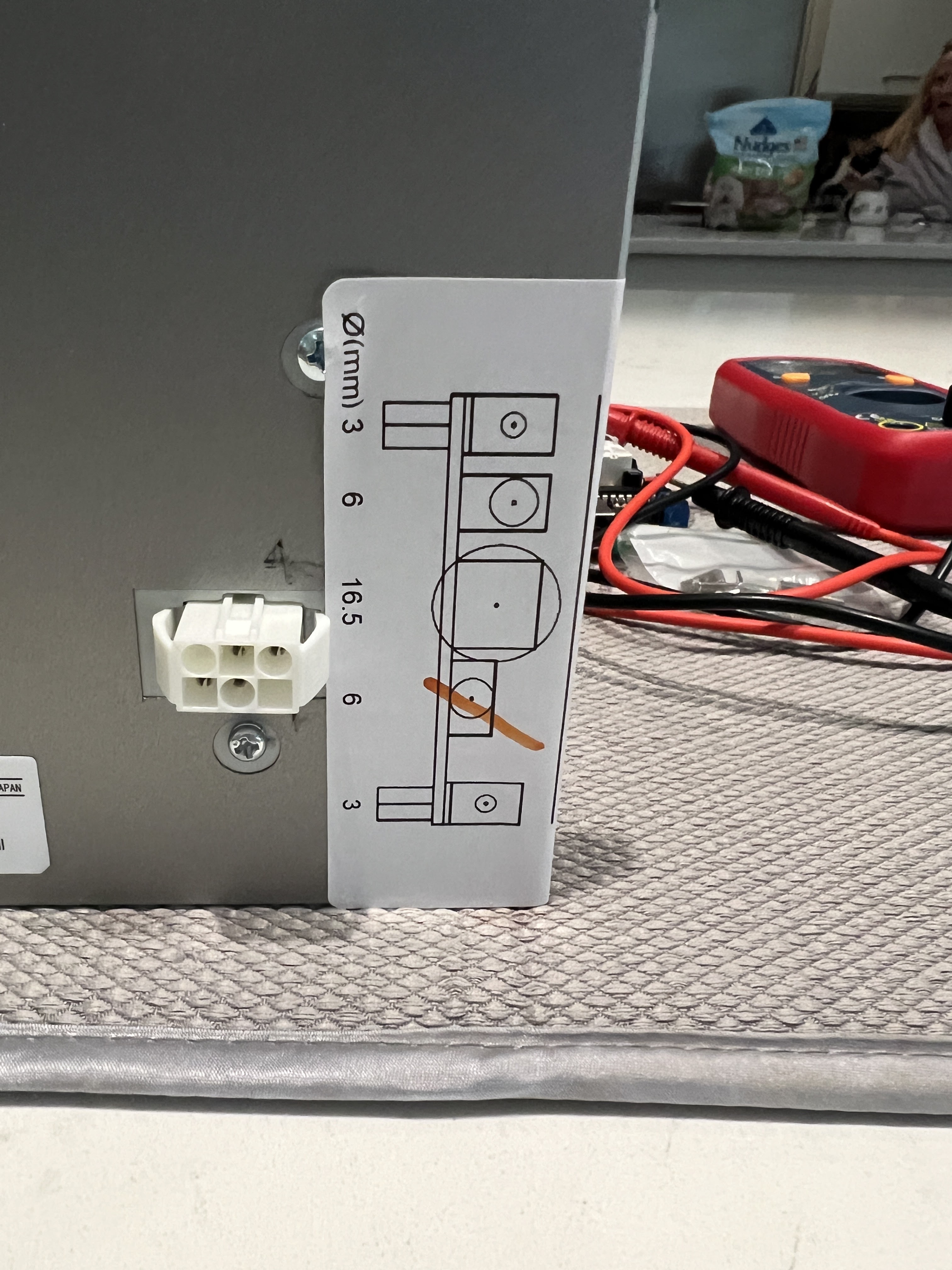
A template is provided with the kit for the holes required to mount the board inside your rotator's control box. I used a step drill bit so that the power, USB and mounting screws were all aligned properly on the metal case.
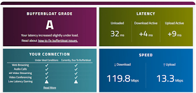
Once the installation and extended calibration was complete, I was able to interface the ERC board to Log4OM v2 for automatic azimuth tracking using PSTROTATER as documented in the Log4OM v2 user manual.
Good luck and 73!
Chris de WX7V
Notes and pictures of the fully assembled ERC v4 board. Wiring schematic for the G-450ADC:


CW Blue 1 Terminal block to bottom tab of S2 Right Switch
CW Blue 2 Terminal Block to top tab of S2 Right Switch
CCW Yellow 1 Terminal Block to CW Blue 1 Terminal Block
CCW Yellow 2 Terminal Block to Top Tab of S3 Left Switch
Yaesu GS-450ADC Control Cable Pinout.
Pin 2 connects to ERC board Green1
Pin 3 to ERC Black1

Template for mounting and connection pass thru.


The ERC board fits nicely and is securely mounted inside G-450ADC controller box.

Clicking the Azimuth turns the antenna to the desired SP (or the LP) of the caller.


Comments